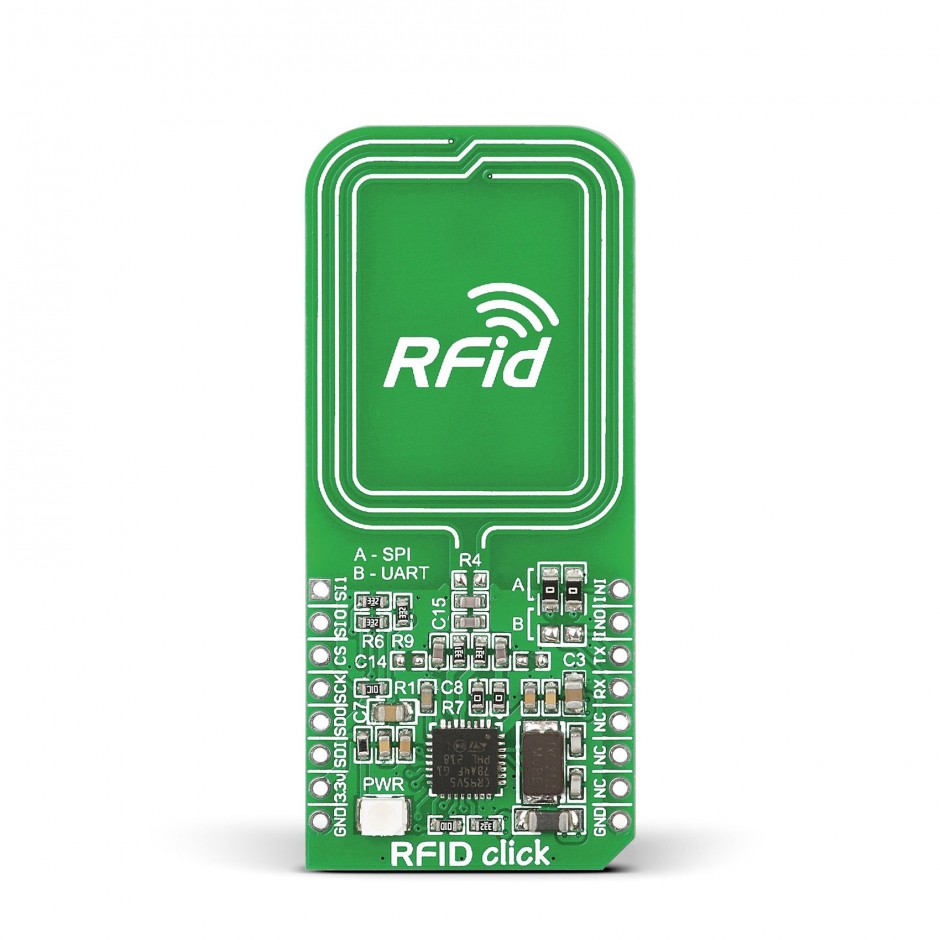
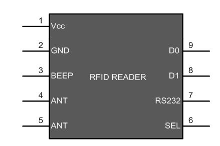
RFID INTERFACING WITH 8051
Radio-frequency identification (RFID) technology enables remote and automated gathering and sending of information between RFID tags or transponders and readers using a wireless link.
Synopsis

Radio-frequency identification (RFID) technology enables remote and automated gathering and sending of information between RFID tags or transponders and readers using a wireless link. An RFID system consists of a reader device and a transponder. A transponder or tag has a unique serial number which is identified by the reader. RFID tag is applied to products, individuals or animals to identify and track them through this number. The interfacing has been done through AT89S52. The identification code of the tag is also displayed on a 16x2 LCD.

Description

The controller to continuously scan the input from the RFID reader. Different RFID tags work on different frequencies. Here low frequency, 125 kHz, RFID tags have been used. These tags work within a range of 10 cm. When an RFID tag comes in this range, the reader detects it and sends a unique code of the tag serially. This serial code, consisting of 12 bytes, is received by the microcontroller. In the program, Timer1 is configured for serial communication. The baud rate is set to 9600bps for data transmission. The LCD is initialized to display the code. When a card/tag comes in the proximity of RFID reader, the microcontroller reads the code and sends it to the LCD module.

When a card/tag comes in the proximity of RFID reader, the microcontroller reads the code and sends it to the LCD module. The serial interrupt is triggered on every reception of one byte of data. Since the identification code of transponder consists of 12 bytes, the flag is also generated 12 times to indicate the byte wise transfer of data. Whenever the serial code is generated by the reader, the interrupt is activated and the data is sent to the receiver pin of microcontroller. A serial level converter is required for AT89S52 to receive these serial signals. IC MAX232 has been used for this purpose to interface the RFID reader with microcontroller.

RFID READER MODULE


Pin Description


With the RFID interfacing, this article also explains the USART interrupt which is an internal interrupt. (For external interrupts, refer PIC Hardware interrupts) The internal interrupts, unlike hardware interrupts, are associated with internal peripherals of the controller. To use the USART interrupt, following registers have to be configured accordingly.

Proteus design for RFID interfacing with 8051


Orcad design for RFID interfacing with 8051


RFID interfacing with 8051

/*  Name     : main.c
 *  Purpose  : Source code for RFID Interfacing with AT89C52.
 *  Author   : Gemicates
 *  Date     : 2017-06-21
 *  Website  : www.gemicates.org
 *  Revision : None
 */
#include <regx52.h>
#include <stdio.h>
#include <string.h>

#define lcd P2		                               // LCD data pins

sbit rs=P1^0;		                               // register select pin
sbit rw=P1^1;		                               // read write pin
sbit e=P1^2;		                               // enable pin

unsigned char card_id[4];		               // ID varialble decleration
                                                       // DELAY FUNCTIONS
		void delay (unsigned int);
                                                       // LCD FUNCTIONS
		void lcddata(char t);                  // lcd functions
		void lcdstring( char *l);
		void lcdcmd(unsigned char);
		void com();
                                                       // RECEIVE FUNCTIONS
		void init();              
		unsigned char* receive();
                                                       // MAIN FUNCTION
void main()
{	 
	unsigned char i,j,k,n;
	unsigned char d[12];
	unsigned char C[12];
	unsigned char c1[12]={0x31,0x31,0x31,0x31,0x31,0x31,0x31,0x31,0x31,0x31,0x31,0x31};
 
	P1=0x00;
	P2=0x00;
	init();
	com();
delay(100);
	lcdstring("ID : ");
	delay(100);
     for(i=0;i<12;i++)		                       // ID value receive function
     {          
			   while(RI==0);
         card_id[i]=SBUF;
				 d[i]=card_id[i];
         RI=0;
     }
	for(n=0;n<12;n++)
	{
		C[n]=d[n];
		lcddata(C[n]);
	}
lcdcmd(0xc0);
k=0;
for(i=0;i<12;i++)
{	
for(j=0;j<12;j++)
	{
			if (c1[i]==d[j])
			{
			 k=k+1;
			}
			else
			{
				k=0;
			}
		}
	}
	if (k>1)
	{
		lcdstring("USER VERIFIED");
		delay(500);
		lcdcmd(0xc0);
	}
	else if (k==0)
	{
		lcdstring("INVALID USER");
		delay(500);
		lcdcmd(0xc0);
	}
}

void init()			                       // UART initialization
{
	TMOD=0x20;
	TH1=0xFD;
	SCON=0x50;
	TR1=1;
}


void delay(unsigned int msec )                         // The delay function provides delay in msec.
{
	int i,j ;
	for(i=0;i<msec;i++)
  for(j=0;j<1275; j++);
}

void lcddata(char t)			               // lcd data function
{
	rs=1;
	lcd=t;	
	rw=0;
	e=1;
	delay(1);
	e=0;
}

void lcdcmd(unsigned char c)		               // lcd command function
{  
	lcd=c;
	rs=0;
	rw=0;
	e=1;
	delay(1);
	e=0;
}

void com()   					       // lcd initialization function
{
	lcdcmd(0x38);
	delay(10);
	lcdcmd(0x0c);
	delay(10);
	lcdcmd(0x01);
	delay(10);
}

void lcdstring(char *d)		                       // lcd string print function
{
	while(*d !=0)
	{
		lcddata(*d++);
	}
}

Error message here!

Show Error message here!


Forgot your password?

Error message here!

Send OTP

Error message here!

Show Error message here!


Lost your password? Please enter your email address. You will receive a password you Need.

Send Error message here!


Back to log-in

Close